 Soil
Soil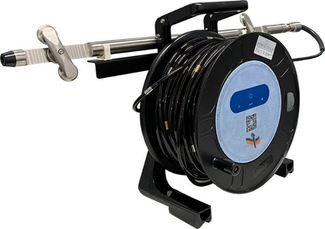
Measure deep horizontal displacement, distributed by depth
The SCIS sliding inclinometer measures how the horizontal displacement of subsurface soil or structures is distributed with depth. A proprietary auto-measurement mode, smart Bluetooth-app interaction and real-time cloud sync completely reinvent the traditional two-person survey workflow.
- ✓Single-operator surveys
Proprietary auto-measurement mode: a 30 m borehole in 5 minutes.
- ✓Bluetooth app + cloud sync
Data flows from field to cloud in real time — zero manual handling.
- ✓Built for harsh sites
IP68 stainless-steel probe rated to 3 MPa (300 m water depth).
How a Sliding Inclinometer Works
The casing is permanently installed in a vertical borehole through the zone of expected movement, with its bottom keyed into a stable stratum as the datum. The probe's gravity-referenced MEMS accelerometer reads the inclination θ at every 0.5 m step; summing each segment's horizontal component from the bottom up rebuilds the full displacement profile.
- 1Pass 1 — A0 direction
The A-axis positive guide wheels run in the A0 groove; reading bottom-up at every 0.5 m records RA0 = sin θ + b, where b is the sensor's zero offset — from residual assembly stress, circuit bias and temperature drift.
- 2Pass 2 — rotate 180°
The probe is withdrawn, rotated 180° about its axis so the same wheels run in the A180 groove, and the survey is repeated: RA180 = −sin θ + b.
- −Subtraction cancels the zero offset
(RA0 − RA180) / 2 = the true sin θ — the zero offset b cancels exactly. That is why both passes are mandatory on the first, baseline survey: a missed reverse pass locks the drift into every later result.
- +Addition yields the checksum
RA0 + RA180 = 2b ≈ 0. The checksum distribution is reviewed before data is delivered: |checksum| < 0.5 mm/m passes; values persistently above the threshold flag instrument zero drift — recalibrate the probe rather than trust the curve.
Curves You Can Act On
After each survey the app jumps straight to plots and data: the casing profile, change versus the baseline and the previous survey, and the checksum distribution — all reviewed on site before the data ships to the cloud.
- ✓Casing profile
Cumulative offset (mm) against depth (m). First check: is the overall shape smooth, with no sudden jumps? A jump usually means a depth was recorded wrongly — check the cable depth markings.
- ✓Cumulative & incremental change
Offset change relative to the first survey reveals displacement trends; change versus the previous survey shows the short-term rate. Overlaying successive surveys shows whether movement is still growing — the key call for early warning, and a way to locate the sliding surface.
- ✓Checksum distribution
Checksum (mm/m) against depth. Before any report is delivered the whole hole should sit within ±0.5 mm/m — the checksum identifies instrument anomalies before they contaminate the displacement record.
Two Classes, One Standard of Quality
Class A serves high-accuracy rail-transit and major energy projects; Class B provides a high-value configuration for routine foundation-pit and slope monitoring.
| Parameter | Class A High-Precision (SCIS Series) | Class B Standard (RCIS/SCIS 20xx) |
|---|---|---|
| Sensor | MEMS accelerometer | MEMS accelerometer |
| Resolution | 0.005 mm / 500 mm | 0.01 mm / 500 mm |
| Repeatability | ±0.003° | ±0.006° |
| System accuracy | ≤±1.5 mm / 30 m | ≤±2.0 mm / 30 m |
| Range | ±30° / ±15° | ±15° / ±30° |
| IP rating | IP68 · 3 MPa | IP68 · 3 MPa |
| Battery life | 80 h | 60–80 h |
| Operating temperature | -20 ~ 70 ℃ | -20 ~ 70 ℃ |
Four Components — Carried in One Hand
1 · Probe
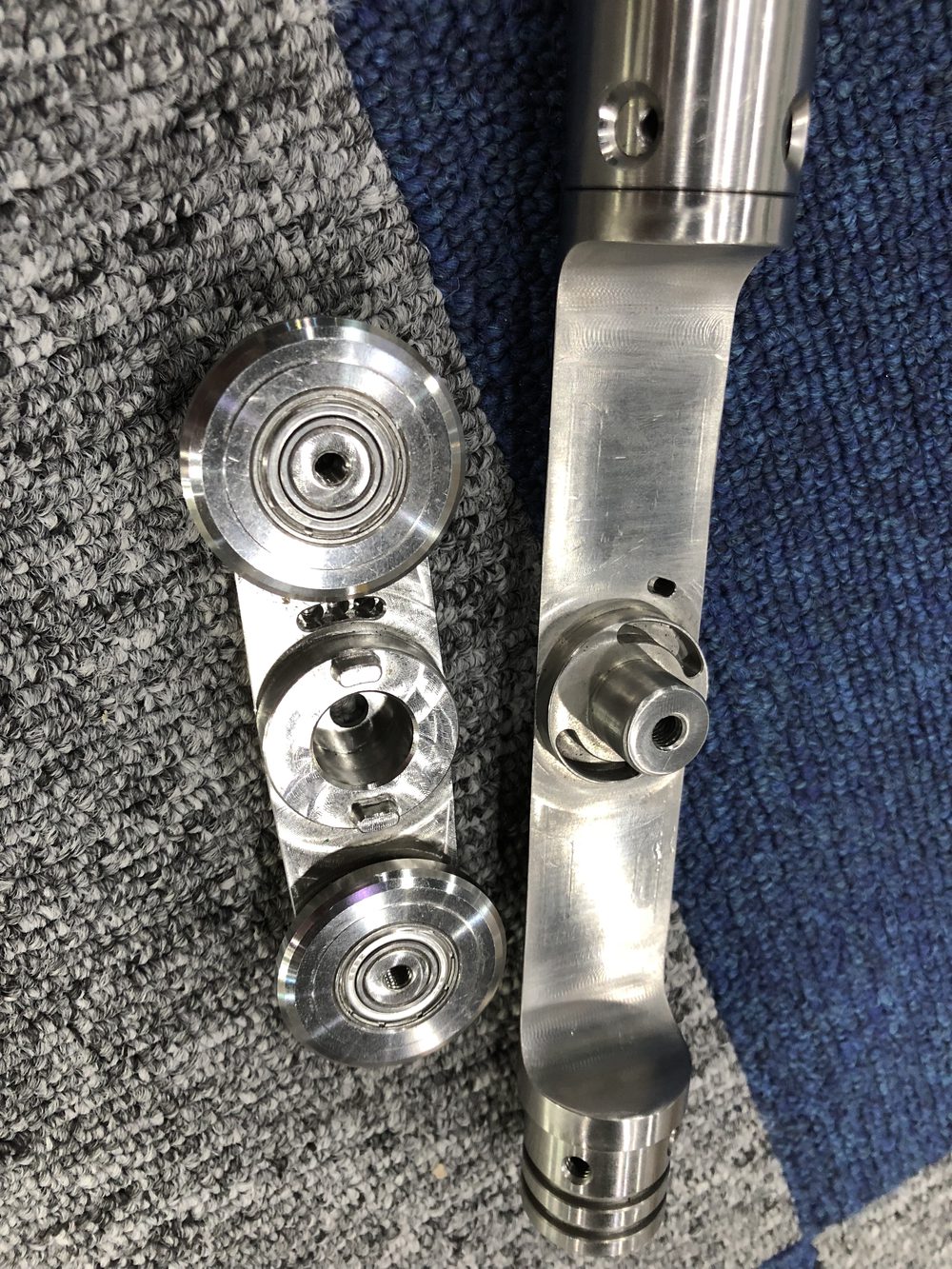
MEMS-sensor probe handles data acquisition in a stainless-steel body.
2 · Control Cable
0.5 m positioning rings provide precise, repeatable depth positioning.
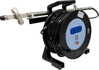
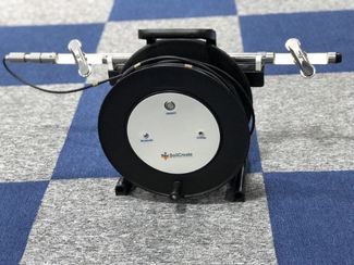
3 · Bluetooth Reel
Built-in 7.4 V lithium battery enables fully wireless transmission.
4 · Mobile App
Android app for processing, on-site plotting and cloud sync.
Auto-Measurement Mode: Just Pull the Probe
The traditional workflow needs two people and 15–20 minutes per borehole. SoilCreate reinvents it — start the app once, then never touch the phone again.
- 1Launch auto-measurement in the app
One tap on an Android phone starts the session.
- 2Software auto-detects stability
Lower the probe to depth; stability confirmed when 3 consecutive readings differ by <0.02 mm.
- 3Auto-record + voice prompt
Once stable, data records automatically and the voice prompt says "Pull now."
- 4Pull detection
Raise the probe 0.5 m — a >0.1 mm change is auto-recognized as a pull, and the next point begins.
- 5Repeat to the top — hands-free
The operator never touches the phone until the survey is complete.
The Complete A0 + A180 Survey, Step by Step
Both passes are mandatory on the first, baseline survey — and the app walks the operator through every step, from Bluetooth pairing to the on-screen checksum.
- 1Power on & pair
Switch on the reel (green power indicator), launch the app on the Android terminal and connect to the Bluetooth device whose RTI-prefixed name matches your instrument — a steady blue light means connected.
- 2Open the project, enter the A0 groove
Tap Measure to open or create the project. Slide the A-axis positive guide wheels into the A0 groove and lower the probe to the starting depth — the cable marking must match the depth shown in the app.
- 3Survey the A0 pass, bottom-up
At each 0.5 m station, wait for the reading to stabilize, record, then pull to the next depth until the probe reaches the top. In auto mode the software detects stability and each pull for you.
- 4Rotate 180°
Withdraw the probe and rotate it 180° about its axis so the A-axis positive wheels enter the A180 groove; lower it back to the starting depth.
- 5Survey the A180 pass
Start the 180° series. The app now shows the live checksum — the A0 + A180 sum, ideally ≈ 0 — beneath each reading as you repeat the pass to the top.
- 6Review plots before leaving site
The app jumps straight to the plots-and-data screen. Check the checksum distribution and profile curves on site; the survey syncs to the cloud automatically.
Five Checks Before Every Survey
1 · Serial-number match
Probe and Bluetooth-reel serial numbers must correspond one-to-one — never mix sets.
2 · Top screw
Don't over-tighten the probe's top screw — it damages the cable connector and shortens O-ring life.
3 · Guided in & out
Use a hand to guide the positioning wheels as they slide into and out of the casing grooves.
4 · Gentle to the bottom
Lower with care so the probe never strikes the casing bottom.
5 · Temperature window
Keep the ambient temperature within −20 to 70 °C.
Quality gates
Checksum |A0+A180| < 0.5 mm/m; same-depth repeatability < 0.3 mm/m; cumulative curve smooth with no jumps.
Head-to-Head with the Industry Benchmark
In a same-borehole comparison at Xinghu Street CX34 (37 m borehole, half a month of testing), SoilCreate's cumulative-change curve closely matched the reference instrument throughout the test period.
| Dimension | SoilCreate SCIS | Reference Instrument |
|---|---|---|
| Readout device | Smartphone app | Dedicated readout unit |
| Operators | 1 person | 2 people |
| Time per borehole | 5 min / 30 m | 15–20 min |
| Data transfer | Bluetooth → cloud, real-time | Manual export |
| System weight | 7.5 kg | ~15 kg |
| Accuracy validation | Xinghu St. CX34 same-borehole match | Industry benchmark |
One operator replaces a two-person crew.
5 minutes vs. 15–20 minutes per 30 m borehole.
Field → cloud with zero touch, eliminating transcription errors.
Same-borehole field comparison with closely aligned curves.
Proven Across Benchmark Projects
Suzhou Metro Line 6
Jinchu Street Station — wall inclinometer monitoring with manual comparison.
Guangzhou Metro Line 13
Shangyong Park Station — foundation-pit monitoring, cross-validated against in-place data.
Hangzhou Metro Line 3
Chaowang Road Station — emergency-response monitoring with automated verification.
Baihetan Hydropower Station
Deep-displacement measurement of surrounding hillsides at a 300 m-class world-scale project.
Xinghu Street CX34, Suzhou
Same-borehole comparison with a reference instrument, with closely aligned data over half a month.
PetroChina Pipeline, Nanning
Geohazard landslide-body monitoring along an operating pipeline corridor.
Sliding Inclinometer FAQ
Is the SCIS compatible with inclinometer casing I already have installed?
How do I choose the control-cable length for deep boreholes?
What should I do when the checksum is abnormal?
Readings take a long time to stabilize, or auto mode saves points by mistake — how do I fix it?
How long does the battery last, and what if Bluetooth won't connect?
How should the probe and cable be maintained — and when must the probe go back for recalibration?
Downloads & Resources
Related Products
Related Cases

Related Solutions

Make an enquiry
Submit your request without leaving the page. Price negotiation stays off the public catalog.
Contact: sales@soilcreate.com · WhatsApp: +86 15356046033