 Soil
Soil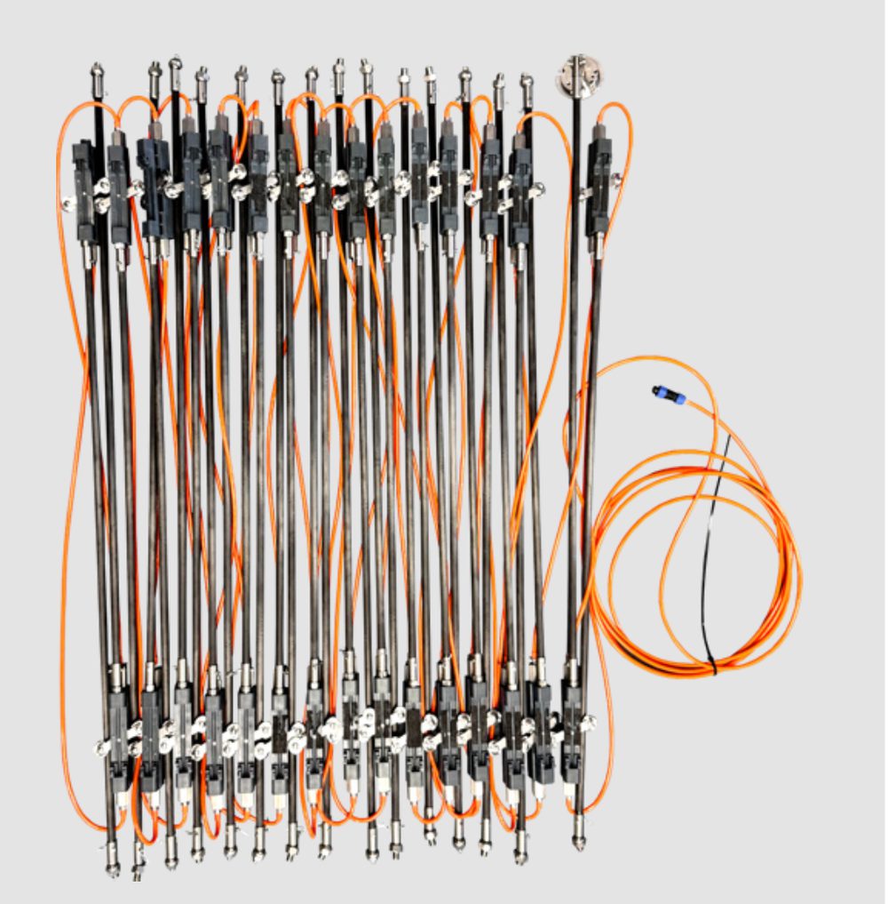
Real-time data that manual surveys can never capture
If the sliding inclinometer solves manual-survey efficiency, the in-place inclinometer answers the need for 7×24 automated monitoring. It samples continuously at minute-level frequency — as fast as one reading per minute — capturing the instantaneous changes a daily site visit could never detect.
- ✓Carbon-fiber rod, 120 g/m
One-fifth the weight of a traditional metal rod — light yet high-strength (≥5.5 kN).
- ✓One RS485 cable, 128 nodes, AutoID
A single bus chains 128 segments; AutoID auto-addressing means no per-unit configuration.
- ✓Electrolytic-solution sensor option
Proprietary sensing element with 1×10⁻⁸-level long-term stability for multi-year projects.
A Permanent Sensor String Inside the Casing
If the sliding inclinometer is a stethoscope lowered into the borehole for each visit, the in-place inclinometer is a permanently implanted ECG: it seals the entire manual-survey process inside the grooved casing and runs it automatically, around the clock.
- ✓Permanent, not periodic
A sliding system competes on flexibility — one probe surveys many boreholes weekly or monthly during construction. The in-place type competes on permanence: installed once, it samples automatically at minute-level frequency with no site visits. Projects running three years or longer, or sites needing remote access, are IPI territory; sub-one-year construction monitoring usually favors the sliding type.
- ✓Segment number ↔ depth, on record
Segments are installed bottom-up, and each one is logged into a segment-number-to-depth table as it goes in. Any later anomaly in the remote data maps straight back to a specific segment at a specific depth — so maintenance targets one node instead of guessing.
- ✓Cloud-managed alarms, automatically
Devices are bound to the cloud platform at the factory; on site, the controller registers and comes online by itself. Engineers then set rate and cumulative alarm thresholds per measuring point — when a reading exceeds them, the platform pushes SMS alerts, with multi-account views for owner, contractor, supervisor and third parties.
What the Data Looks Like
Each segment continuously measures tilt over its gauge length; the platform converts the chain of readings into a displacement-vs-depth profile. Because sampling is automatic — as fast as one reading per minute — the profile is redrawn continuously, revealing how deflection develops over time instead of waiting for the next manual survey.
On network loss, each string buffers data in 16 GB of onboard storage — over a year of history — and resumes upload automatically once the connection recovers.
Built for Unattended, Long-Term Duty
Two figures stand out: 0.05 W per segment means the system runs stably on solar power alone, and 5.5 kN tensile strength keeps deep-borehole installation structurally safe.
| Parameter | SCIS-IPI-01 Specification |
|---|---|
| Sensor | MEMS accelerometer / electrolytic-solution sensor (optional) |
| Range | ±15° / ±30° |
| Resolution | 0.01 mm / 0.005 mm |
| Repeatability | ±0.003° |
| Long-term stability | <±0.01% |
| Operating temperature | -20 ~ 70 ℃ |
| Waterproof rating | IP68 / 2 MPa |
| Power consumption | ≤0.05 W / segment |
| Tensile strength | ≥5.5 kN |
| Rod length | 0.79 m / 1 m |
| Net weight | ~1 kg / segment |
"Light yet Strong" — the Design Philosophy
While holding 5.5 kN tensile strength, the carbon-fiber rod cuts weight to one-fifth of a traditional metal rod — so operators install in 60–100 m deep boreholes by hand, with no hoisting equipment.
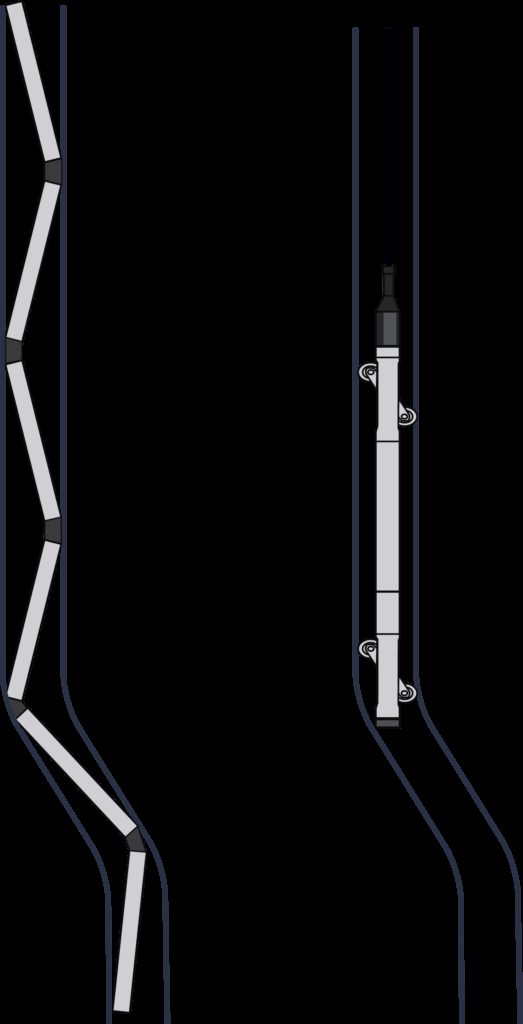
- 1Centralizing wheel set
Fixed wheels plus spring-loaded wheels keep the sensor precisely aligned in the casing.
- 2Rod — carbon fiber / aluminum alloy
120 g/m, one-fifth the weight of a traditional metal rod, with deep anodized corrosion protection.
- 3High-precision tilt sensor
The core measuring element: MEMS, or the proprietary electrolytic-solution sensor for ultimate long-term stability.
- 4Universal joint connection
Flexibly links the segments to accommodate a degree of casing bend.
- 5Positioning cable + casing-mouth fixture
Anchors and protects the entire sensor string.
Bus Connection
One RS485 cable chains 128 segments. Each sensor ships with a factory-unique long address; AutoID assigns short addresses on site — plug-and-play, no per-unit configuration.
Smart Automation
Scheduled sampling configurable from 1 min to 24 h; ultra-low-power sleep mode; breakpoint-resume on network loss with 16 GB local storage; remote configuration and firmware upgrades.
Long-Term Stability
Even the best MEMS accelerometers drift at the 1×10⁻⁵ level over the years; SoilCreate's proprietary electrolytic-solution sensor holds 1×10⁻⁸ — three orders of magnitude less drift, ideal for 5-year-plus monitoring.
In-place + sliding, better together: the in-place type captures instantaneous changes in real time (such as tidal fluctuations); the sliding type cancels zero drift with forward-and-reverse runs. Combined, they form the most complete deep-displacement monitoring solution.
Installation: 12 Steps, Bottom-Up
Before starting: identify the string's top (the segment with the aviation-plug cable) and bottom (no plug), and clamp the steel wire rope to the bottom segment. Three checkpoints gate the whole procedure — fixed-wheel orientation, connecting-rod engagement, and steel-wire-rope lock-off.
- 1Compress the spring-loaded wheels
Press the moving-wheel springs on the segment firmly before it enters the casing.
- 2Slide the wheel set into the guide grooves — checkpoint
The fixed wheels must face the expected deformation direction of the excavation. Wrong orientation distorts all subsequent data.
- 3Mate the connecting rod — checkpoint
Carefully insert the quick-connect port of the rod above the segment onto the metal connecting rod — fully seated, no gap. Any gap is an error source.
- 4Tension and lock the steel wire rope — checkpoint
Pull the wire rope through the rod fully taut, then lock the segment's rope clamp. An untensioned rope leaves segments unloaded and lets them drop out of position.
- 5Secure the spare cable
Wind excess cable around the connecting rod and fasten with cable clips, so it cannot rub against the casing wall.
- 6Lower and connect the next segment
Push the rod down, then insert the next segment's bottom metal rod into the quick-connect port — again with no gap.
- 7Repeat for every segment
Repeat steps 1–5 segment by segment, bottom-up, until the string is complete.
- 8Lead out the top cable
Bring the top segment's cable and aviation plug out through the side slot of the casing-mouth protector.
- 9Seat the casing-mouth protector
Place the protector into the casing with its rim pressed onto the casing mouth.
- 10Tension the top wire, tighten the screws
Pull the wire rope above the protector until fully fixed, then tighten the butterfly screws on the protector.
- 11Stability check before power
Visually confirm the whole system sits firmly in the casing before energizing anything.
- 12Power up and go online
Connect power and the controller, then bring the string online on the cloud platform — and verify the first remote reading before leaving site.
The Three Gates
1 · Fixed-wheel orientation
The fixed wheels must face the excavation's expected deformation direction. Installed the wrong way, readings persistently trend to one side — and the only remedy is re-installing with the correct orientation.
2 · Connecting-rod engagement
Every metal connecting rod must be fully seated in its quick-connect port with no gap. A loose segment-to-segment joint is a permanent error source.
3 · Steel-wire-rope lock-off
Tension first, then lock the rope clamp. If the rope will not pull through, the previous segment's clamp is still locked — open it before pulling. An untensioned rope leaves segments unloaded and out of position.
Field rule: no matter how tight the schedule, if any of the three checkpoints — fixed-wheel orientation, rod engagement, wire-rope lock-off — is wrong, stop and redo it. Continuing and patching later always costs more than redoing now.
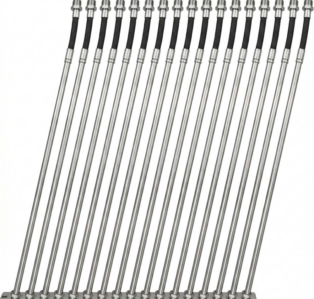
Hardware Up Close
World-Leading Accuracy · High-Value Pricing
SCIS-IPI-01 combines a 128-node RS485 bus, AutoID addressing and a 120 g/m carbon-fiber rod. The result is less field wiring, simpler deep-borehole installation and a system designed for long-term automated monitoring.
| Dimension | SoilCreate SCIS-IPI-01 | Conventional Multi-Cable Systems |
|---|---|---|
| Wiring | One RS485 cable for 128 segments | Multi-core cable, one run per sensor |
| Signal & addressing | Digital bus + AutoID auto-addressing | Analog signal, per-unit configuration |
| Rod weight | Carbon fiber, 120 g/m | Metal rod, ~5× the weight |
| Deep-borehole install | Single person, by hand, 60–100 m | Heavier string, hoisting often needed |
| Offline resilience | 16 GB storage, breakpoint-resume, remote upgrade | Depends on external logger |
| Commercial model | High-value project pricing | Varies by system and service scope |
Carbon fiber vs. a traditional metal rod.
One RS485 line replaces 128 cable runs.
Electrolytic-solution option vs. ~1×10⁻⁵ for the best MEMS.
World-leading accuracy in a project-ready system.
Where Real-Time Data Proved Its Worth
SoilCreate in-place inclinometers have supported long-term deep-displacement monitoring at major energy, foundation-pit and rail-transit projects. Minute-level automated sampling preserves changes that periodic manual surveys can miss.
Coastal Energy Site — the "Ocean Breathing" of a 107 m Borehole
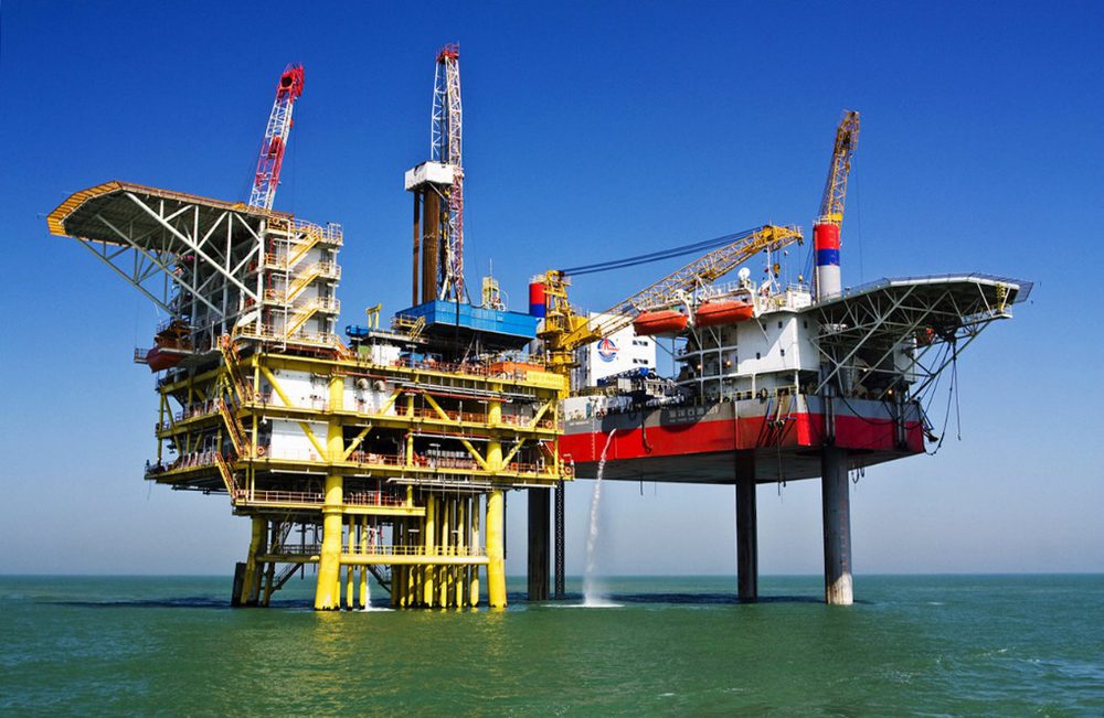
In reclaimed soft soil 23 m from the sea, automated monitoring recorded an approximately 12-hour periodic casing-top movement with an amplitude near 100 mm. The continuous series provided clear evidence for identifying the influence of Ocean Tide Loading.
Suzhou Xiangcheng Foundation Pit
Long-term automated monitoring captured twice-daily periodic displacement of the retaining structure, closely matching the tides — deformation that once-a-day manual surveys could never reveal.
Suzhou Metro Line 5
A deformation-rate exceedance triggered a Level III alert — pushed by SMS and app to the responsible parties before the construction team had noticed anything abnormal. The system is faster, and more accurate, than people.
Frequently Asked Questions
What kind of casing does the in-place inclinometer require?
No data is coming through after power-up — what should we check first?
The data keeps trending to one side — is the sensor drifting?
Who sets the alarm thresholds, and can they be changed later?
MEMS or electrolytic-solution sensor — which should a multi-year project choose?
If remote data turns anomalous, how do you locate the problem segment?
Downloads & Resources
Related Products
Related Cases
Related Solutions

Make an enquiry
Submit your request without leaving the page. Price negotiation stays off the public catalog.
Contact: sales@soilcreate.com · WhatsApp: +86 15356046033