 Soil
SoilFlexible Inclinometer (Shape Array, SAA)
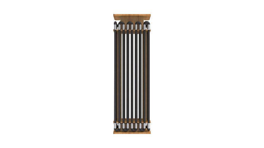
A spine-structure 3D deformation monitoring array for large deformation and complex conditions. Segmented like building blocks, it can be assembled on site, dismantled at project end and redeployed on the next project.
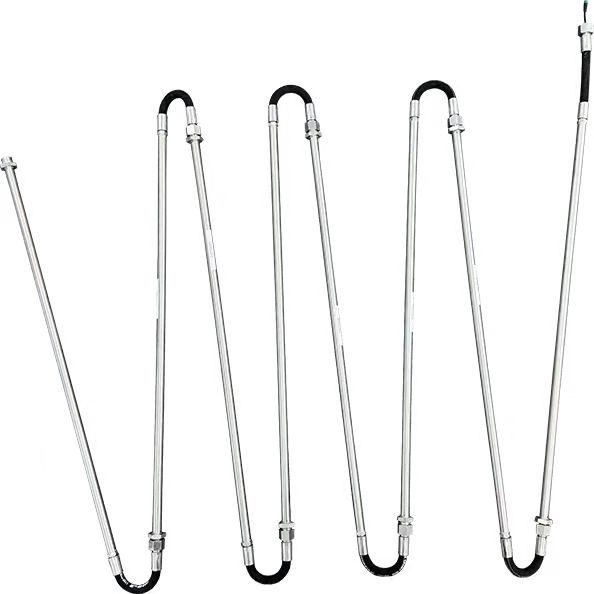
3D deformation, segmented & recoverable, multi-mode layout
The SCIS-SAA-02 measures displacement in X, Y and Z simultaneously through a spine-structure array of rigid sensing segments and flexible hinges. AutoID + RS485 chain up to 128 segments on a single cable — vertical in a borehole, horizontal in a trench, or ring-laid around a tunnel section.
- ✓3-axis measurement, 0–360° coverage
Full all-direction sensing with no blind spots — hard to exceed range even in large deformation.
- ✓±0.002° measurement accuracy
Equivalent to 0.02 mm per 500 mm, with 0.005 mm displacement resolution.
- ✓180° maximum bending
Flexible hinges naturally adapt to curved layouts — tunnels, ring sections, uneven trenches.
- ✓IP68 · 3 MPa, tested to 4 MPa
Backed by a Ministry of Water Resources 4 MPa test report; 8 MPa custom available.
A Spine of Rigid Segments and Flexible Joints
Rigid sensing tubes alternate with flexible joints — the tubes measure, the joints take the deformation. Each rigid segment carries a 3-axis MEMS sensor that measures its own orientation in space across 0–360°; chaining every segment's vector end-to-end reconstructs the full 3D deformation shape of the borehole or structure.
01 · Sense
Every rigid segment measures its 3-axis orientation across 0–360° and logs its own temperature in real time.
02 · Flex
Flexible joints between segments take the bending, so measurement and deformation are cleanly separated.
03 · Reconstruct
Segment vectors are chained into the 3D shape curve; torsion correction aligns all segments to one coordinate system, better than 0.5°.
A Continuous Profile, One Point per Segment
Every rigid segment is a measurement point, so the array returns a continuous displacement profile with no blind spots — and because acquisition is automated, the deformation trajectory can be replayed in real time as it develops.
Full Technical Specifications
Segment lengths of 0.3 m, 0.5 m or 1 m to match your measurement-density requirements, with sampling up to 10 kHz for dynamic events.
| Parameter | Specification (SCIS-SAA-02) |
|---|---|
| Measurement dimensions | 3D (X/Y/Z) |
| Angular range | 0 ~ 360° |
| Measurement accuracy | ±0.002° (0.02 mm / 500 mm) |
| Displacement resolution | 0.005 mm |
| System stability | ±0.3 mm / 30 m |
| Max bending angle | 180° |
| Segment length | 0.3 m / 0.5 m / 1 m options |
| Segments per cable | Up to 128 (AutoID auto-addressing) |
| Communication interface | RS-485 (Modbus RTU) |
| Ingress protection | IP68, 3 MPa water pressure (tested to 4 MPa) |
| Operating temperature | -40 ~ 60 ℃ |
| Sampling rate | Up to 10 kHz |
Designed for Reuse, Integration and Field Service
SCIS-SAA-02 uses field-assembled segments, so system length can follow each project and individual sections can be inspected, replaced or redeployed. This reduces transport, installation and lifecycle constraints common to fixed-length arrays.
| Dimension | SoilCreate SCIS-SAA-02 | Conventional Fixed-Length SAA |
|---|---|---|
| Sensor | MEMS / high-end electrolytic-solution sensor | MEMS sensor |
| On-site assembly | Segment-based field assembly; length adjusted on site | Factory-defined length; adjustment depends on supplier |
| Recovery & reuse | Designed for segment recovery and project-to-project redeployment | Depends on installation method and product configuration |
| Installation | Centered installation in inclinometer casing | Installation method varies by project |
| Protection | 4 MPa standard; 8 MPa available by configuration | Varies by model |
| Data access | Direct raw-data interface for system integration | Depends on the vendor software ecosystem |
| Weight | ~0.6 kg/m | Varies by configuration |
| Commercial model | High-value project pricing with reusable hardware | Imported-system pricing and service model |
Lower transport, hoisting and on-site handling effort.
World-leading accuracy with pricing designed for engineering deployment.
Dismantle, inspect and redeploy the array after project completion.
Vertical, horizontal and ring layouts from one product.
Three Deployment Modes, One Product
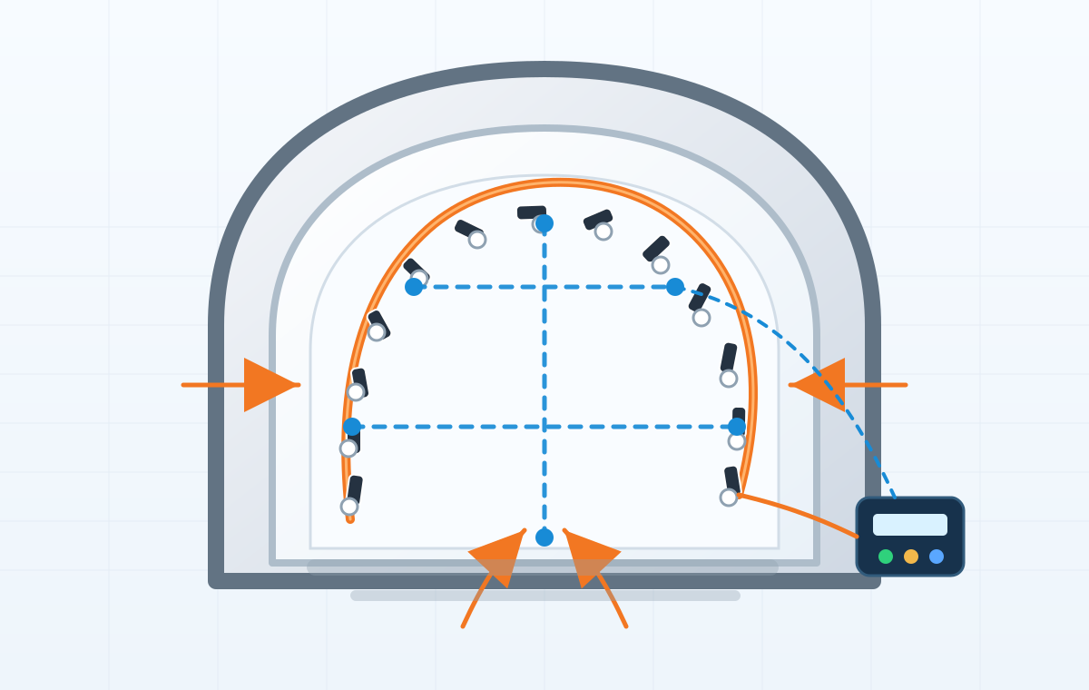
Vertical for inclinometry, horizontal for settlement, ring for convergence — the flexible structure adapts wherever rigid probes cannot go.
Vertical · Inclinometry
Deep displacement of foundation pits and slopes. Drops straight into the inclinometer casing — no guide wheels needed. The most common scenario.
Horizontal · Settlement
Settlement of subgrades and rockfill dams — buried in a trench inside a PVC conduit, pulled in by wire rope from one end.
Ring · Convergence
Tunnel cross-section convergence — laid circumferentially along the wall or lining segments; the flexible structure naturally follows the curve.
Built around two core capabilities
- ✓Segmented & recoverable
Segmented design → flexible on-site assembly → dismantled & recovered at project end → transported to the next project → lower hardware amortization cost.
- ✓Torsion correction
Built-in algorithm detects axial torsion → auto-computes azimuth → aligns to a unified coordinate system → correction accuracy better than 0.5°.
- ✓AutoID + RS485 bus
One cable chains up to 128 segments with automatic addressing — simple wiring, open protocol, ready for any logger or platform.
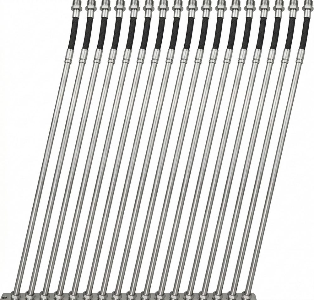
Installation: Vertical & Horizontal Paths
The deployment modes above tell you where the array goes — this is how it gets there. Vertical (chained in casing) and horizontal (trench-laid) follow two entirely different procedures that are not interchangeable: confirm which one applies before work starts.
Vertical — chained inside the casing
- 1Prepare the casing
Seal the casing bottom and fill the casing with clean water.
- 2Connect the controller
The lead-out cable at the top of the array connects to the controller.
- 3Lower top-down
Lower the array into the casing from the top; slight bending is allowed at each flexible joint.
- 4Fix and protect
Fix the array at the top and fit a protective device on the casing mouth.
- 5Casing twist self-corrects
If the casing twists during monitoring, the rotation it imparts to the array is corrected automatically by the torsion-correction algorithm.
Horizontal — trench + PVC conduit
Ships as a kit: PVC conduit matched to the run, end caps and mouth fittings, traction wire rope and marker posts.
- 1Excavate the trench
Trench bottom flat and level, length matched — avoid local dips.
- 2Lay the conduit
Every PVC conduit seam must be sealed with PVC primer + cement — otherwise water gets in later.
- 3Pull in — never push
Pull the array into the conduit with the wire rope from one end. Pushing destabilizes the flexible joints and damages the hinges.
- 4Check every bend radius
At any curve the bend radius must stay ≥ Rmin (about 0.3 m); any section below the limit is re-laid.
- 5Finish & seal
Waterproof the lead-out end and seal the end caps.
After Burial: Remote Inspection for Horizontal Layouts
A horizontal run leaves nothing visible at the surface — periodic inspection happens remotely on the cloud platform.
Review the overall displacement-curve shape remotely every week.
Compare readings against same-period per-segment temperature records.
Verify benchmark stability to separate true displacement from foundation movement.
Send for a metrology-institute spot calibration every year.
Assembly & Structure in Detail
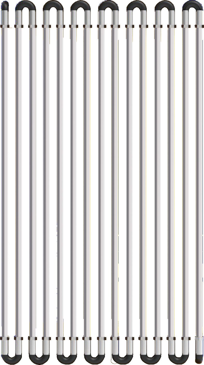
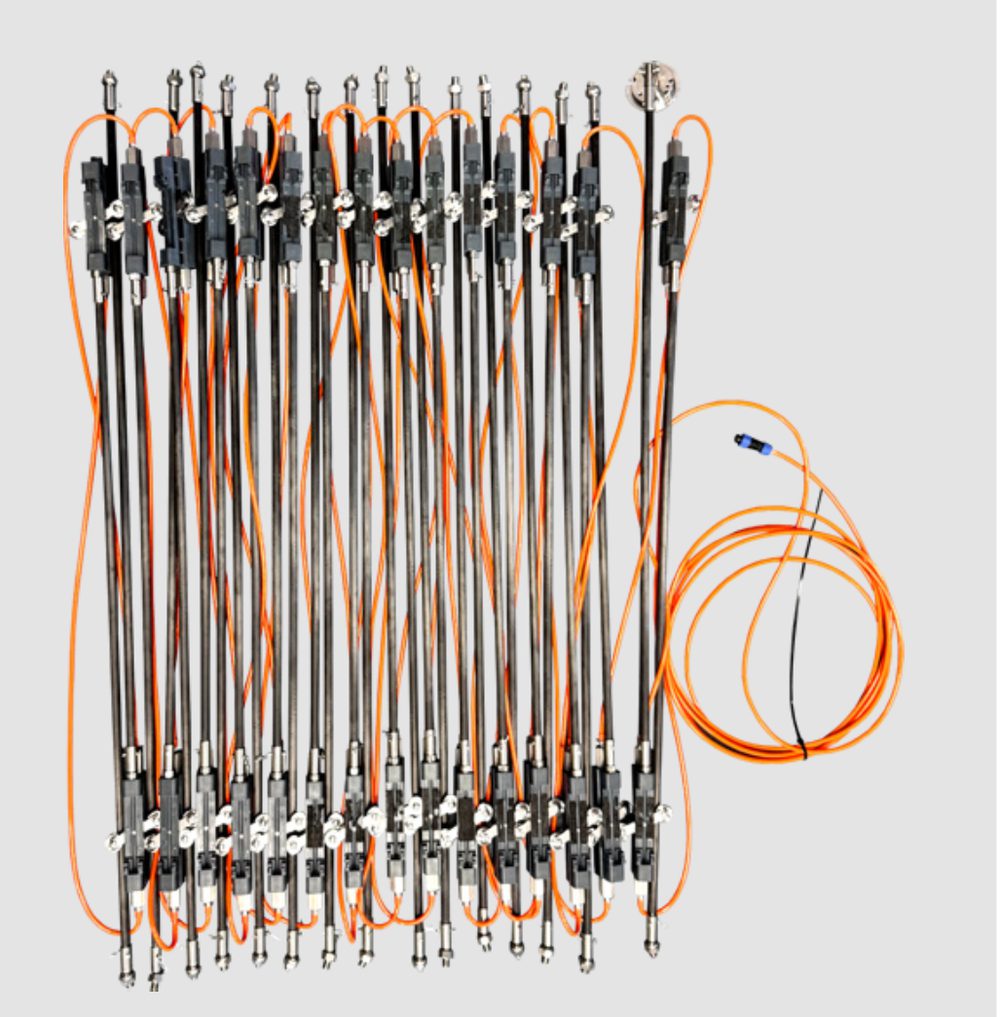
Every Segment Is a Reusable Asset
Recovered segments can be inspected and configured for a new project, allowing the same hardware investment to serve multiple deployments and reducing lifecycle cost with each reuse.
Modular assembly — installed by 2 people in 30 minutes.
Automated acquisition, zero manual effort.
Dismantled and recovered segment by segment.
Hardware cost falls with each reuse.
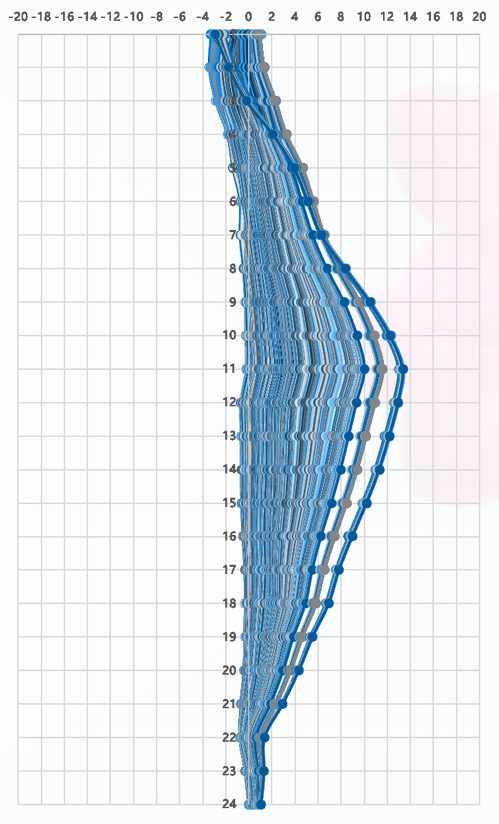
Real monitoring output: cumulative deep-displacement profiles — depth on the vertical axis, displacement on the horizontal; successive automated readings trace the deformation history.
Shaoxing Metro Line 2: validated against the sliding inclinometer
At Paojiang Lianghu Station, a flexible and a sliding inclinometer were installed just 20 cm apart in the same borehole. Over six months, A-axis displacement trends matched closely — proving automated SAA monitoring can fully replace manual sliding surveys with equally reliable data.
- ✓Method
Two sensor types buried 20 cm apart in the same borehole.
- ✓Duration
6+ months of continuous monitoring.
- ✓Result
A-axis trends matched closely; the two datasets mutually verified.
SAA or In-Place Inclinometer — Which to Choose?
A simple rule: complex large deformation, settlement or convergence — choose the flexible SAA. Vertical deep boreholes where small displacements matter — choose the in-place inclinometer. Combining the two delivers the best results.
| Feature | Flexible Inclinometer (SAA) | In-Place Inclinometer (IPI) |
|---|---|---|
| Structure | Flexible joints, bendable | Rigid rod, must stay straight |
| Measurement density | Continuous, no blind spots | Discrete (1–3 m spacing) |
| Range | 0–360°, hard to exceed range | ±15° / ±30° |
| Deployment | Vertical / horizontal / ring | Mainly vertical |
| Weight | ~0.6 kg/m | Carbon fiber 0.12 kg/m (lighter) |
| Best for | Complex large deformation / settlement / convergence | Small displacements in vertical deep boreholes |
Monitoring a vertical deep borehole with small displacements? Explore the In-Place Inclinometer →
Four Benchmark Case Studies
From same-borehole validation to a tidal pattern no human survey could ever catch — each case proves a different capability.
Shaoxing Metro Line 2 · Paojiang Lianghu Station
Flexible and sliding inclinometers installed 20 cm apart in the same borehole. Six months of monitoring: A-axis trends matched closely — automation reliably replaces manual surveys.
Suzhou Metro Line 5 · Jinchu Street Station
Automated monitoring triggered a displacement-rate alert, catching sudden displacement from delayed strut installation — proof of high-frequency response to sudden conditions.
Suzhou Xiangcheng Foundation Pit
High-frequency sampling revealed twice-daily periodic fluctuation of the retaining structure — a tidal deformation pattern undetectable by manual surveys, linking groundwater level to structural deformation.
Baihetan Hydropower Station · Ultra-Deep Borehole
High-precision monitoring in a 300 m-class ultra-deep borehole, operating stably long-term in harsh conditions — product reliability proven under extreme conditions.
More deployments: Hangzhou Metro Line 3 · Qingdao Jiaozhou Bay Tunnel (65 units) · Shanghai Metro Line 18 · Nanning CNPC pipeline geohazard monitoring
Frequently Asked Questions
Horizontal settlement profiles or tunnel convergence rings — flexible array or in-place inclinometer?
Does vertical installation need inclinometer casing with guide grooves?
What is the minimum bend radius?
Can I push the array into the conduit on a horizontal run?
How does recovery and reuse work between projects?
How is axial torsion handled?
How do I inspect and maintain a horizontal layout once it is buried?
The whole curve jumped — or has drifted slowly for months. What does each signature mean?
Downloads & Resources
Related Products
Related Cases
Related Solutions

Make an enquiry
Submit your request without leaving the page. Price negotiation stays off the public catalog.
Contact: sales@soilcreate.com · WhatsApp: +86 15356046033