 Soil
SoilSettlement Monitoring
Hydrostatic level gauges across three measurement principles and three range bands — 0.01 mm resolution, ranges to 2000 mm — plus layered settlement gauges for subgrade consolidation, covering everything from routine foundation pits to precision engineering.
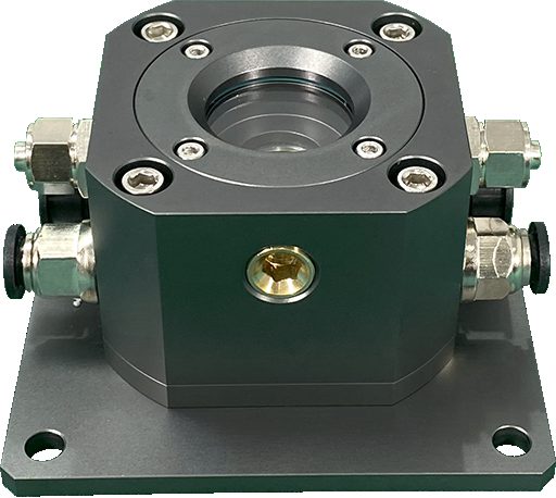
Sub-millimeter settlement, from one pit to a whole district
Hydrostatic leveling networks measure each point's settlement relative to a stable reference cell using the connected-vessel principle. SoilCreate offers three sensing principles — differential-pressure, magnetostrictive and ultrasonic — so the right physics is matched to each project's range and accuracy needs. On most structures they are deployed together with our tiltmeter series for a complete deformation picture.
- ✓Three principles, three range bands
From 0–200 mm best-value monitoring to 0–2000 mm extra-large range and ultra-high-accuracy non-contact measurement.
- ✓0.01 mm-class resolution
Resolves the slow, small settlements that decide whether a structure is safe — long before they are visible.
- ✓RS485 to DAQ & cloud
Every gauge feeds the SoilCreate data loggers and Monitoring Cloud for automated, unattended operation.
One Liquid Loop, One Stable Reference
Every gauge in the network is joined at the bottom by a liquid line and at the top by a separate air line, forming a system of communicating vessels: at rest, all liquid surfaces settle to one common level H₀. When monitoring point i settles, its sensor moves down relative to that shared surface and the liquid column above it grows — the cell reads ΔPᵢ = ρ·g·(H₀ − z_sensor,i), so settlement is sᵢ = (ΔPᵢ − ΔPᵢ,₀) / (ρ·g). The glycol working fluid (≈1050 kg/m³) carries a density temperature correction ρ(T) = ρ₀[1 − β(T − T₀)], β ≈ 4×10⁻⁴/°C.
Everything is relative to the reference
Hydrostatic leveling outputs settlement relative to the reference cell. If the reference itself moves, the whole network drifts with it — so the reference goes on long-term stable bedrock and its own stability is re-verified by periodic leveling surveys. When all points drift in the same direction at once, suspect the reference first.
The magnetostrictive variant: absolute position
SCST02 reads its float magnet by time-of-flight on a magnetostrictive alloy waveguide (FeNi, TbDyFe): a microsecond current pulse meets the magnet ring's axial field, and the Wiedemann effect launches a torsional strain wave traveling at ≈2850 m/s toward a detection coil (inverse Wiedemann / Villari effect). Position is x = v·Δt — 100 ps timing resolves 0.3 µm, drift stays under 5 ppm/°C, and because position is absolute, the reading is retained through power loss.
Three Principles, One Family
Differential-pressure for best value, magnetostrictive for extra-large range, ultrasonic for the most demanding accuracy — together they cover the full spectrum of settlement projects.
| Parameter | Differential-Pressure (SCST01) | Magnetostrictive (SCST02) | Ultrasonic |
|---|---|---|---|
| Principle | Connected-vessel differential pressure | Magnetostrictive time-of-flight, absolute position | Non-contact ultrasonic |
| Range | 0–200 mm | 0–2000 mm | approx. 100 mm |
| Resolution / accuracy | 0.01 mm resolution | 0.01 mm accuracy | Ultra-high accuracy |
| Output | RS485 | RS485 | RS485 |
| Key strength | Best value for money | Extra-large range; reading retained on power loss | No contact with the liquid surface |
| Best for | Foundation-pit settlement | Large-area precision settlement: metro operation, building clusters | Precision engineering settlement |
Engineered So the Data Can Be Trusted
Most hydrostatic-leveling failures happen at installation, not in the sensor. Our delivery process enforces the details that keep a network honest for years.
Independent liquid & air lines
Liquid and air tubes are always routed separately — sharing one conduit causes siphoning and silently invalidates the whole network. We never compromise on this.
Reference cell on stable ground
Every settlement value is relative to the reference cell, so it is installed on long-term stable bedrock and periodically re-verified by leveling surveys.
Temperature-corrected fluid
Readings carry a fluid-density temperature correction, and antifreeze concentration is re-checked on a 1–2 year cycle for cold-climate reliability.
See How Each Soil Layer Consolidates
Surface settlement tells you how much; layered settlement tells you where. Magnet rings embedded at target depths track each stratum independently — essential for subgrade filling, surcharge preloading and construction above shield tunnels.
- 1Magnet rings anchored to the soil
Each ring is set at a target depth with opening claws that grip the surrounding stratum — so it moves with the soil, not with the access tube.
- 2Manual probe reading
A reed-switch probe lowered down the access tube locates each ring to ±1 mm — a simple, economical routine for short-term construction monitoring.
- 3Vibrating-wire automation
A vibrating-wire option upgrades resolution to 0.05 mm and removes site visits entirely — built for long-term, remote operation.
- 4Layer-by-layer consolidation curves
Depth-resolved settlement time series show exactly which stratum is still consolidating — the evidence engineers need to release the next construction stage.
| Dimension | Magnet-Ring Manual | Vibrating-Wire Automated |
|---|---|---|
| Accuracy | ±1 mm | ±0.05 mm |
| Site visits | Weekly readings | None — fully remote |
| Installation effort | Low | Moderate |
| Best for | Short-term construction | Long-term operation |
Typical deployments: expressway subgrade, airport runways, surcharge-preloading programs and ground above shield-tunneling drives.
Settlement & Tilt: Pick the Right Product in One Glance
Settlement and tilt are usually monitored together on the same structure. This matrix covers both — tiltmeter details are on the Tiltmeter Series page.
| Application Scenario | Recommended Product | Why |
|---|---|---|
| Foundation-pit settlement | Differential-Pressure Level Gauge (SCST01) | Best value for money |
| Large-area precision settlement | Magnetostrictive Level Gauge (SCST02) | Extra-large 0–2000 mm range |
| Precision engineering settlement | Ultrasonic Level Gauge | Ultra-high accuracy, non-contact |
| Layered subgrade consolidation | Layered Settlement Gauge (RLS) | Depth-resolved, layer-by-layer settlement |
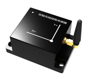
| Dilapidated building / tower tilt | Wireless Tiltmeter (LoRa) | Cable-free deployment, long battery life |
| High-support formwork / tunnel | Wired Tiltmeter (RS485) | Higher accuracy, continuous acquisition |
| Bridge tilt monitoring | Wireless Tiltmeter (NB-IoT) | More reliable remote transmission |
The Install Gates That Keep a Network Honest
None of these checks can be done at the factory — each one is confirmed on site, item by item, before the system goes live.
- 1Keep every cell within range of the loop
Mount the reservoirs so height differences stay inside the sensor's range — beyond it, the differential-pressure output saturates.
- 2Route liquid and air lines separately
Never share one PU conduit. A shared line creates a siphon: air squeezes the liquid column into interrupted flow and the whole network fails at once. This rule has no exceptions.
- 3Put the reference cell on stable bedrock
All values are relative to the reference — install it on long-term stable bedrock and re-verify its stability with periodic leveling surveys.
- 4Fill to level and purge air
Inject working fluid until every reservoir level is in place. A cell with trapped air bubbles reads erratically — re-bleed until the reading stabilizes.
- 5Set the antifreeze verification cycle
Check or replenish antifreeze concentration every 1–2 years — concentration drifts with evaporation and refills, and an under-strength fluid freezes in cold climates. Check before winter, not after the first freeze.
Magnetostrictive cells: three boundaries
The magnet ring slides over the waveguide but must never touch it — contact damages the alloy waveguide and scraps the unit. Keep clear of welders, variable-frequency drives and heavy-current cables, and flag-and-exclude data logged during welding work. A single waveguide runs to 7.5 m at most; beyond that, switch to a segmented scheme. All three are confirmed at selection stage — discovering them on site usually means changing the model.
Layered settlement (RLS): set right before grouting
Pre-embed the access tube in the borehole at its design position. Slide each magnet ring over the outside of the tube with its claws opened to grip the surrounding stratum — an unanchored ring follows the casing, not the soil, and every "settlement" it reports is false. Record each ring's as-built depth against its stratum number before sealing the hole — a depth mismatch is the most fatal error in later data interpretation. On the vibrating-wire version, equalize the external spring pre-tension across points, or initial values carry a systematic offset into the whole history.

Field Questions, Straight Answers
Compiled from our after-sales records and the fault tables in the field manuals.
All points are drifting in the same direction — is the whole site settling?
One point's reading keeps jumping around.
Readings respond sluggishly to known movement.
What maintenance does the liquid loop need — especially in cold climates?
Our magnetostrictive gauge jitters or spikes — is it broken?
A layered-settlement magnet ring suddenly shows a centimeter-level shift.
Downloads & Resources
Related Products
Related Cases

Related Solutions

Make an enquiry
Submit your request without leaving the page. Price negotiation stays off the public catalog.
Contact: sales@soilcreate.com · WhatsApp: +86 15356046033