 Soil
SoilVibrating-Wire Sensors & Acquisition
A one-stop stress-monitoring solution: six vibrating-wire sensor families plus an intelligent frequency-sweep acquisition system that also reads most other vendors' VW sensors — from foundation-pit struts to dam cores.
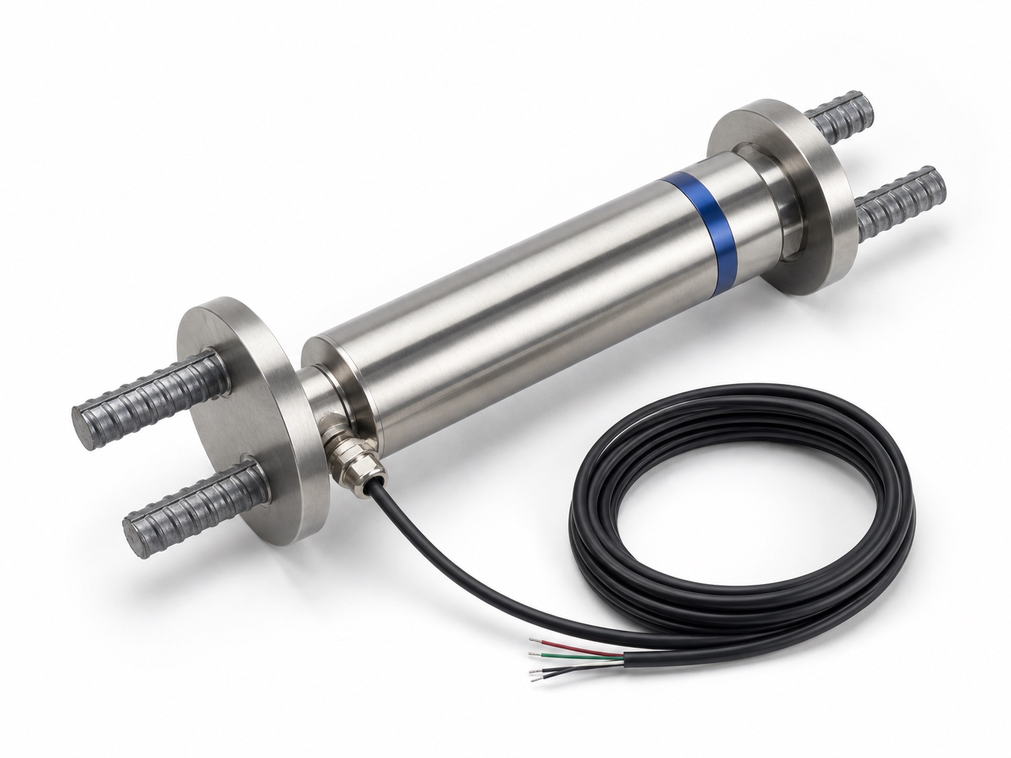
Frequency-based sensing that stays stable for decades
Vibrating-wire sensing converts stress, strain and pressure into the resonant frequency of a tensioned steel wire — a signal immune to cable-length attenuation, resistant to electromagnetic interference and nearly drift-free over years. That is why it remains the de-facto standard for permanently embedded monitoring of foundation-pit supports, tunnel linings, dam bodies and bridge pile foundations.
- ✓Engineered for permanent embedment
Frequency output is unaffected by long cables and EMI; long-term drift stays below 0.1% FS per year.
- ✓Synchronized temperature compensation
Every sensor carries a built-in thermistor sampled together with frequency, stripping thermal effects out of the stress reading.
- ✓One family, every stress parameter
Rebar stress, surface and embedded strain, anchor-cable load, earth pressure and pore water pressure — all on one acquisition system.
How a Steel Wire Measures Stress
A steel wire 0.15–0.20 mm thick and 100–150 mm long is tensioned between two end blocks fixed to the structure. Its resonant frequency follows f = (1/2L)·√(T/ρ): wire tension is proportional to f², so any strain in the member shifts the frequency — a principle in continuous dam-monitoring service since the 1930s.
Pluck, Then Listen
The coil fires a 1–5 kHz frequency-sweep pulse to set the wire ringing, then switches to receive mode. The ring-down at the wire's resonant frequency induces a 1–10 mV signal from which frequency is extracted by zero-crossing counting or FFT.
Frequency, Not Voltage
Because the measurand is a frequency rather than an analog voltage, the signal is immune to long-cable attenuation and electromagnetic interference — the physical reason VW sensors survive decades of permanent embedment in concrete.
Temperature, Stripped Out
A 10 °C swing can bias an uncompensated stress reading by 5–10%. The built-in NTC thermistor (typ. 10 kΩ at 25 °C) is sampled synchronously with frequency, and the k_T term in the formula strips the thermal effect out.
Inside the piezometer, the same wire sits behind a stainless-steel diaphragm: water pressure deflects the diaphragm by a few micrometres, a push rod converts that into wire tension, and pressure follows P = G·(f² − f₀²) + Δ_T·(T − T₀) — a two-stage mechanical amplification that underpins its decade-scale stability.
Six Families, One-Stop Stress Monitoring
From rebar stress to pore water pressure, the vibrating-wire family covers the stress-monitoring needs of nearly every geotechnical structure.
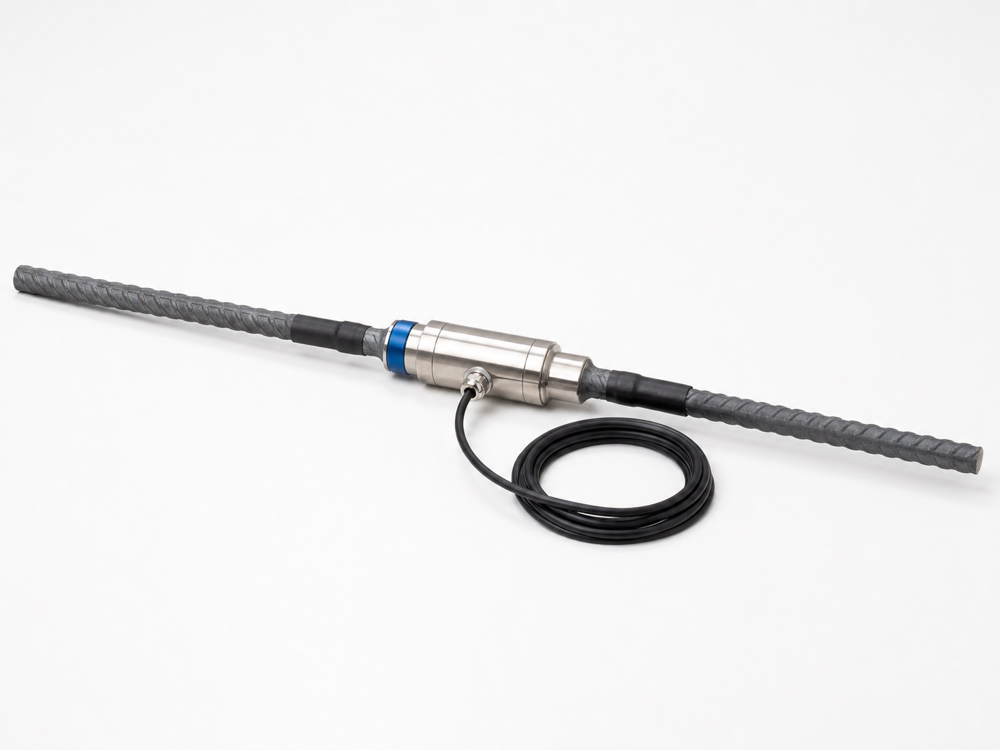
Rebar Stressmeter
Monitors rebar stress on the vibrating-wire principle — welded in line with the reinforcement before casting.
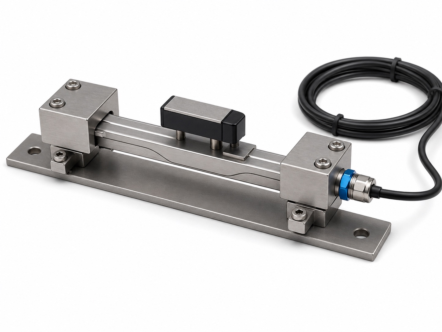
Surface Strain Gauge
Mounts directly on the structure surface to measure strain on existing concrete and steel members.
Concrete Stressmeter
Embedded during casting to track long-term stress changes inside concrete members and mass-concrete structures.
Anchor-Cable Load Cell
High-range design monitors the load on anchor cables and rock bolts in slope and excavation support systems.
Earth Pressure Cell
Diaphragm sensing measures soil pressure against retaining structures and within embankment fills.
Piezometer
Pore-water-pressure monitoring with a 0–4 MPa range; the diaphragm-plus-wire stage delivers 0.025% FS resolution.
SCSE-VW01 Series: The Hub Between Sensors and Cloud
Three configurations — SCSE-VW01 (16-ch), 8-channel and 4-channel variants — digitize vibrating-wire signals and hand them to the data gateway and cloud platform. A handheld re-survey unit (handheld verification unit) covers manual on-site verification.
- ✓Intelligent frequency-sweep
Automatically matches each sensor's resonant frequency — a clear advantage on long cables and in strong electromagnetic interference.
- ✓High-voltage excitation
Programmable high-voltage excitation keeps signals stable and reliable, even with slowly degrading sensor coils.
- ✓Plug-and-play, multi-vendor compatible
Auto-detects sensor type and reads coils from 50 Ω to 10 kΩ — most vendors' VW sensors connect with no replacement needed.
- ✓Built-in temperature channel
Thermistor channels sample synchronously with frequency for accurate temperature compensation.
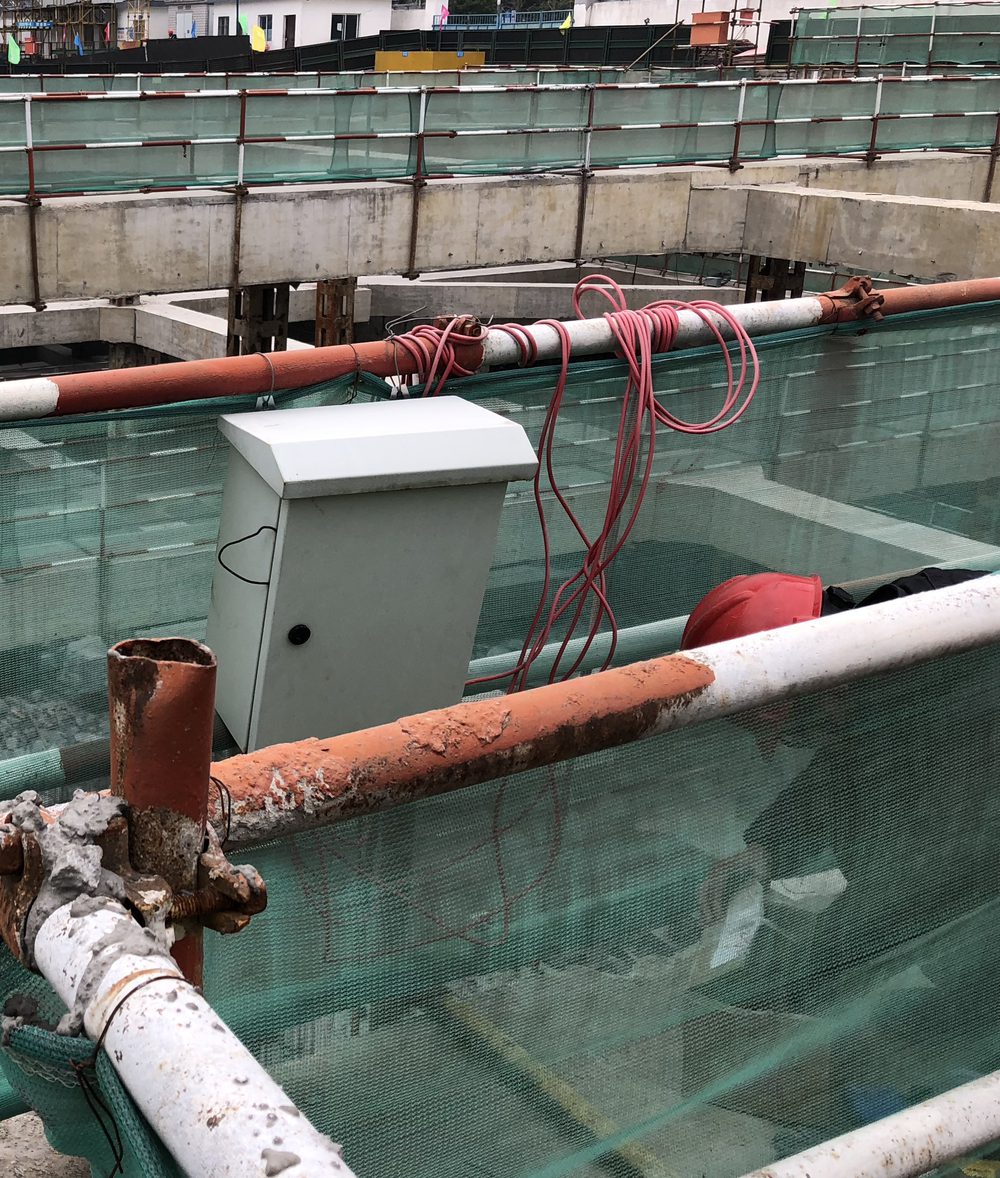
From Wire to Cloud in Four Hops
1 · VW Sensor
Stress, strain or pressure changes the steel wire's resonant frequency.
2 · Acquisition Module
Sweep-excites the wire, reads the ring-down and digitizes frequency plus temperature.
3 · Data Gateway
Uplinks over 4G / RS485 with local buffering against network loss.
4 · Cloud Platform
SoilCreate Monitoring Cloud handles curves, tiered alerts and reports.
Acquisition Module Specifications
| Parameter | SCSE-VW01-4 (4-Channel) | SCSE-VW01 (16-Channel) |
|---|---|---|
| Frequency range | 1000–5000 Hz | 1000–5000 Hz |
| Excitation | Programmable high-voltage | Programmable high-voltage + programmable & intelligent frequency-sweep |
| Sensor auto-ID | Coils 50 Ω – 10 kΩ | Coils 50 Ω – 10 kΩ |
| Temperature element | Thermistor (customizable) | Thermistor (customizable) |
| Uplink | 4G / RS485 | 4G / RS485 |
| Power supply | Built-in 8.4 V lithium battery | 9–24 V solar / mains |
| Operating temperature | -20 ~ 60 ℃ | -20 ~ 70 ℃ |
Embedment & Field Practice
Sensor accuracy and installation accuracy are two different things: a piezometer leaves the factory at 0.025% FS, but an unsaturated filter or a mis-recorded depth can put 5–10% of error into the data. These field rules close that gap.
- 1Saturate the filter under water — at least 24 h
A piezometer's porous filter is never lowered dry. Residual air bubbles bias long-term readings low by 5–10%, and no later calibration can recover it.
- 2Two gates before concrete embedment
A 48-hour burn-in plus independent verification with a frequency meter. Once the concrete is poured there is no second chance.
- 3Record the actual depth to 0.1 m
The installed depth must match the design documents — a wrong depth record is the hardest error to trace in later data back-analysis.
- 4Seal the borehole above the sensor
Sand or bentonite sealing prevents water from connecting across layers; without it, the measuring point loses its layer-specific meaning.
- 5Choose gauge vs. absolute correctly
Vented (gauge) types for water-level work — atmospheric pressure is removed automatically; absolute types for sealed, confined water pressure. The wrong choice makes the data oscillate with the weather.
Already Own Another Vendor's VW Sensors?
SoilCreate acquisition terminals use an open protocol and identify any vibrating-wire sensor with a coil resistance from 50 Ω to 10 kΩ — covering Geokon, Sisgeo, Roctest, Maihak and mainstream domestic brands. Existing sensors connect to the SoilCreate Monitoring Cloud without replacement.
Lost Contact After Embedment? Don't Break Concrete First
The field triage order: switch to intelligent frequency-sweep, step the excitation voltage level, verify independently with a frequency meter — and only then consider physical access. Intelligent sweep often recovers sensors with slowly degrading coils.
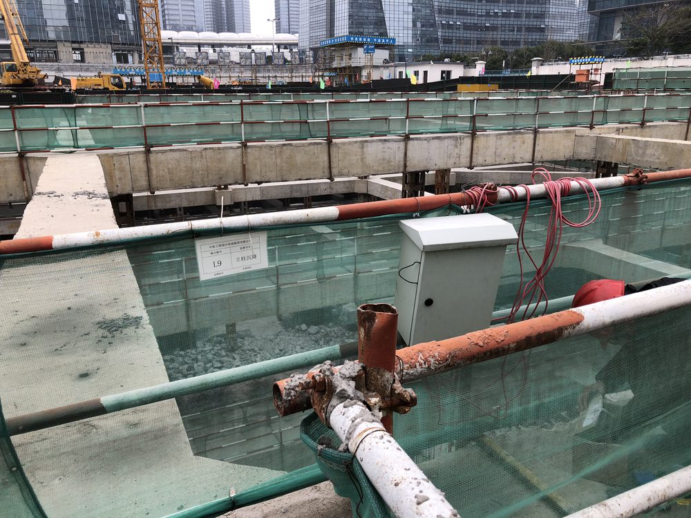
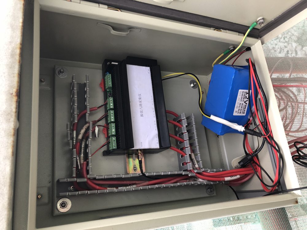

Automated Water Level Monitoring System
Two sensing principles: pressure-sensitive SCST-WL Series at 0.5% FS accuracy, and vibrating-wire SCSE-VW01-PZ for long-term stable monitoring — covering foundation-pit, reservoir and groundwater levels.
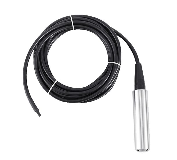
- ✓Integrated design, no trenching
The all-in-one unit drops straight into the standpipe — no trenching or surface wiring required.
- ✓Automatic temperature compensation
Built-in compensation keeps readings accurate through seasonal and day-night temperature swings.
- ✓RS485 + 3-month battery life
Standard RS485 communication interface with over three months of operation per charge.
- ✓Part of a complete pit-safety system
Pairs with inclinometers and VW sensors to assess dewatering, detect leakage and track groundwater trends.
Frequently Asked Questions
Can SoilCreate loggers read vibrating-wire sensors from other vendors?
Do long signal cables degrade the reading?
Why does temperature compensation matter so much?
The channel reads zero frequency, or the frequency is unstable — what do I check?
Our piezometer reads consistently low after installation. Why?
Why does our pore-pressure data move with the weather?
Downloads & Resources
Related Cases

Related Solutions

Make an enquiry
Submit your request without leaving the page. Price negotiation stays off the public catalog.
Contact: sales@soilcreate.com · WhatsApp: +86 15356046033